Product Description

20dBm GSM900 WCDMA2100 MHz Dual Band Mobile Signal Booster Cell Phone Repeater Booster
|
Specification |
Uplink |
Downlink |
|
|
Frequency |
GSM&EGSM |
890 ~ 915MHz |
935 ~ 960MHz |
|
WCDMA |
1920 ~ 1980MHz |
2110 ~ 2170MHz |
|
|
Operation Bandwidth |
Wide Band |
||
|
Gain |
≥65dB |
≥70dB |
|
|
Output Power |
≥17dBm |
≥20dBm |
|
|
MGC (Manual Gain Control) |
31dB Range/1dB step |
||
|
Ripple in Band |
8dB |
||
|
Noise Figure |
≤ 6dB |
||
|
VSWR |
≤2.0 |
||
|
Automatic Level Control |
20dB |
||
|
Intermodulation Products |
≤ -40dBc |
||
|
Spurious Emission |
9KHz~1GHz |
≤ -36dBm/30KHz |
|
|
1GHz~12.75GHz |
≤ -30dBm/30KHz |
||
|
Frequency stability |
≤ 0.01ppm |
||
|
MTBF |
> 50000 hours |
||
|
Time Delay |
≤1.5μs |
||
|
Impedance |
50Ω |
||
|
Power Supply |
Input: AC 110~240V; Output: DC 9V/5A |
||
|
LED Alarm |
Power LED |
DC ON/OFF |
|
|
Smart LED |
Smart function ON/OFF |
||
|
AGC Alarm |
Alarm RED when ALC 5dB-10dB |
||
|
ISO Alarm |
Alarm RED when ALC 20dB-25dB, Then Repeater will Auto Shut Down. Auto restart after two minutes. |
||
|
Mechanical Specification |
|||
|
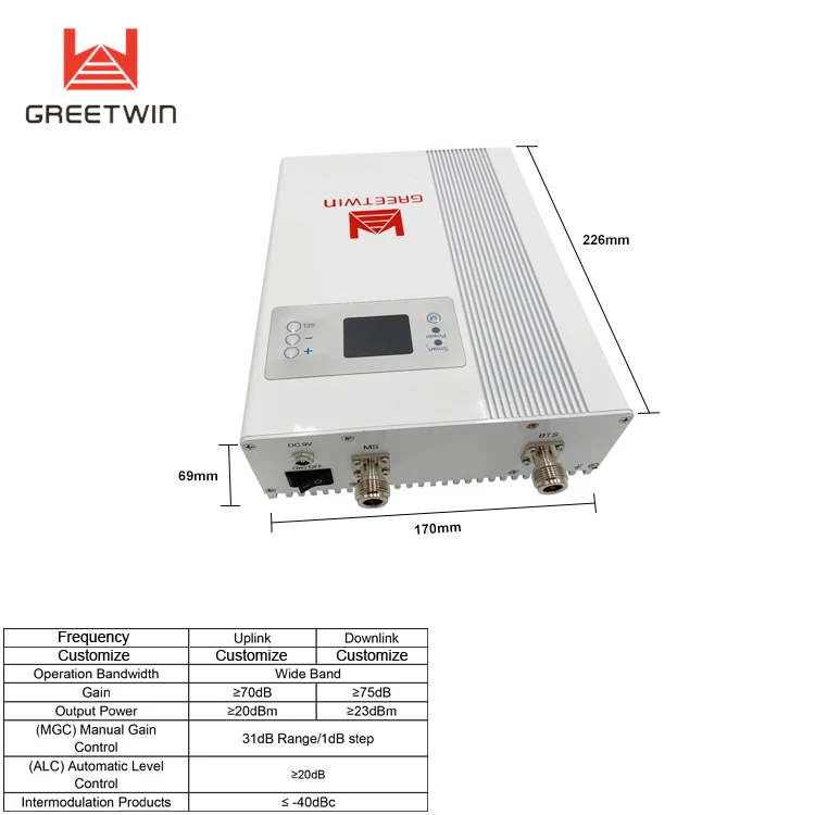
RF Connector |
N-Female |
||
|
Power Consumption |
25W |
||
|
Operating Temperature |
-10℃~ +55℃ |
||
|
Environment Conditions |
IP40(Indoor) |
||
|
Installation Type |
Wall Installation |
||
|
Dimensions (D x W x H ) |
228*170*65mm |
||
|
Weight |
≤ 4 KG |
||

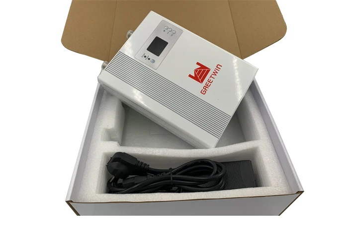
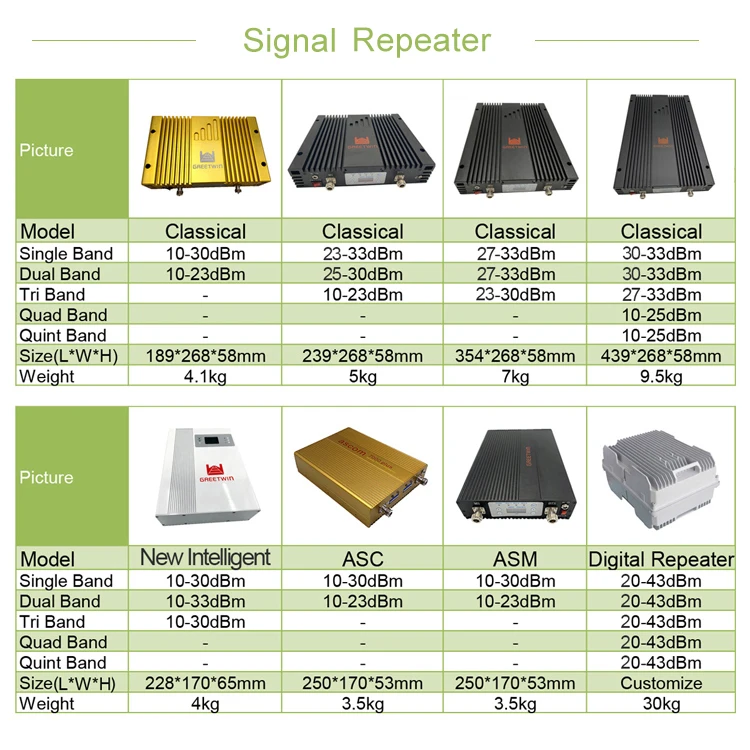
Description:
Mobile wireless networks offer great convenience to people’s communication. However, people often suffer from communication interruption or failure due to mobile phone wireless signal loss or weakness that are always caused by the shadow effect of wireless signal transmission and the buildings shielding effect on the electromagnetic wave. The situation also exists in remote area with few base stations or beyond base station coverage.
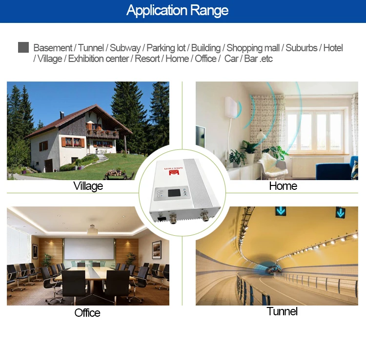
The LCD Repeaters is a newly designed solution with intelligent functions. It is the perfect solution for providing a wireless improvement in the cellular reception of a home, office, restaurant, building or shopping mall. The covering area is ranging up to 1500 square meters.
The LCD Repeater covers all existing wireless public communications networks:
(E)GSM 900MHz, WCDMA 2100MHz.
Features:
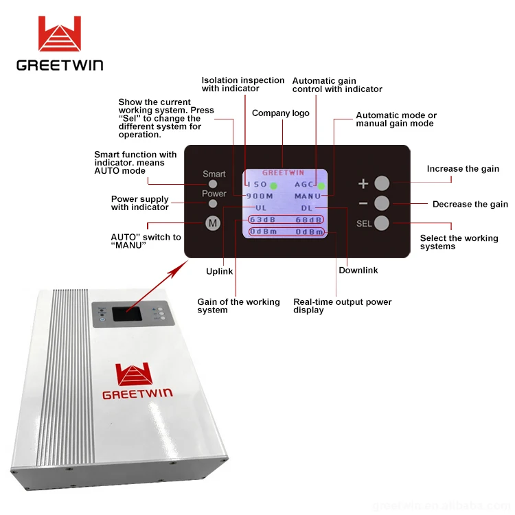
1. Isolation Inspection. When first power on the repeater, the device will automatically detect the isolation between the donor antenna and service antenna. The users could easier see the status and make the adjustment accordingly.
2. Input&Output Signal Strength Indication. The specific number of uplink and downlink measured in Output Power(dBm). Easy for users’ understanding.
3. Manual Gain Adjustment. The users or engineers could reduce the gain of the repeater manually via the buttons below the screen. The uplink and downlink gain could be set independently. “+” is increasing the gain, “-” is decreasing the gain.
4. Automatic Gain Control. Automatic Gain Control (AGC) is a dynamic gain adjustment feature with 31dB range.
5.Smart Mode = AUTO Mode. The repeater could automatically change the gain according to the specific environment when the smart function is on. Please note that when the SMART is on, users could not able to set the gain manually. Gain reduce 31dB automatically at first, then AGC Alarm RED when AGC control 5dB-10dB, ISO Alarm RED when AGC control 20dB-25dB, Repeater will Auto Shut Down. Auto restart after two minutes.
6. MANU Mode, users can set the gain manually. AGC Alarm RED when AGC control 5dB-10dB ;
ISO Alarm RED when AGC control 20dB-25dB, Repeater will Auto Shut Down.
Auto restart after two minutes.
7. Auto Shut Down = ISO. Auto Shut Down is a stage that temporarily stops the RF function. If the input power reduces to a safe range for the repeater to operate, the software would power the repeater back on and restore all functions promptly. However, if the input power remains too great and dangerous for the network, it will then shut down completely. In such case, the signal is too strong for the usage of the repeater.
Application Diagram:
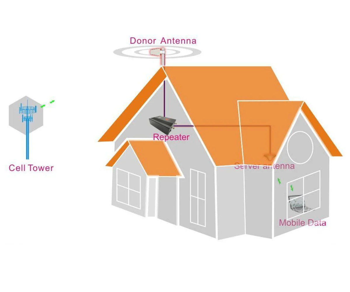
1) Donor antenna: Recommend to use wide band panel antenna (7~14dBi gain) or Yagi antenna, better to use antenna with good direction, high gain, and decoration shall be considered if it is in urban areas.
2) Role: It picks up signals from the tower, and sends to the booster through cables, at the same time, it transmits the amplified mobile signals from the booster to the tower.
3) Server antenna: Recommend to use indoor omni or panel antenna. Indoor omni is suitable for wide open areas where the signals can be radiated from the center to the surroundings, while indoor panel is suitable for those narrow and long areas, like tunnels, corridors, elevators, etc.
4) Cables: 5D-FB or 7D-FB coaxial cables.
5) Power supply: Booster power adapter, a desktop standard. Usually directly connected to a power outlet. But preferably equipped with an air switch, groundings, sometimes a surge arrestor shall be connected.
Product Recommended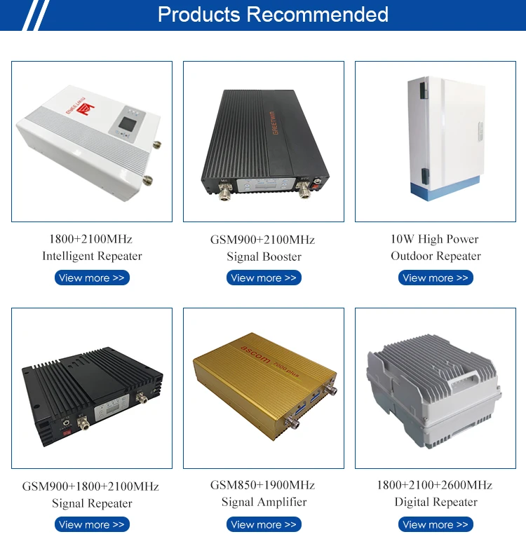




Q1. Why is there still no signal after installing the equipment?
1. Check the power on booster and power supply.
2. Check the connector of outdoor antenna is tight or not.
3. Check the connectors of RF cable are tight or not.
4. Check the outdoor signal is strong enough or not.
5. Check to make sure the antenna is installed correctly.
6. Check the connector of indoor antenna is tight or not.
7. Check the cable type is suitable or not.
Q2. Why the signal strength is too weak on the edge of area?
1. Check the outdoor signal and antenna direction.
2. Check booster is full gain or not.
3. Check all of the connectors are tight.
4. Change the location of outdoor/indoor antenna.
5. Check the cable type is suitable or not.
6. Deploy more indoor antennas.
Q3. After running booster, why the signals are not stable?
1. Checking the distance between donor antenna and server antenna are too close to each other? Check LED
of booster to make sure alarms are green.
2. Checking the signals from donor antenna whether to be stable or not?
3. Connect the system again if it is incorrect connection.
Q4. Why the booster power LED is not bright?
1. Checking the input AC power range indicated on power adapter whether is corresponding to the local
power system.
2. Checking the power adapter whether connect the equipment correctly and stably or not.
3. Checking the power adapter whether damage or not. To test output voltage whether be corresponding to
that indicated on power adapter or not by multimeter