
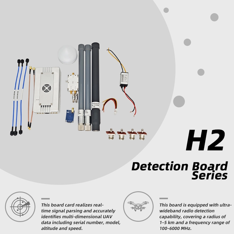
Passive Drone Detection Module DM-H1 600MHz-6GHz UAV Detector
UAV Detection and Positioning Module Real Time Drone Speed Altitude Flight Track Monitoring
View productThis page is written for the people who buy repeaters rather than browse them: importers, integrators and tender teams who need to specify a unit, sample it and then order at volume. Everything below belongs to the same 800 / 900 / 1800 / 2100 / 2600 MHz indoor repeater, from its band plan and 70/75 dB gain class through to the documents worth requesting before you sign off a batch. If you are sourcing a cell signal booster for resale, the band matrix and output class decide which variant you stock. If you are specifying a cellular signal booster for an office or basement project, the installation and coverage notes below decide how the job should be planned.
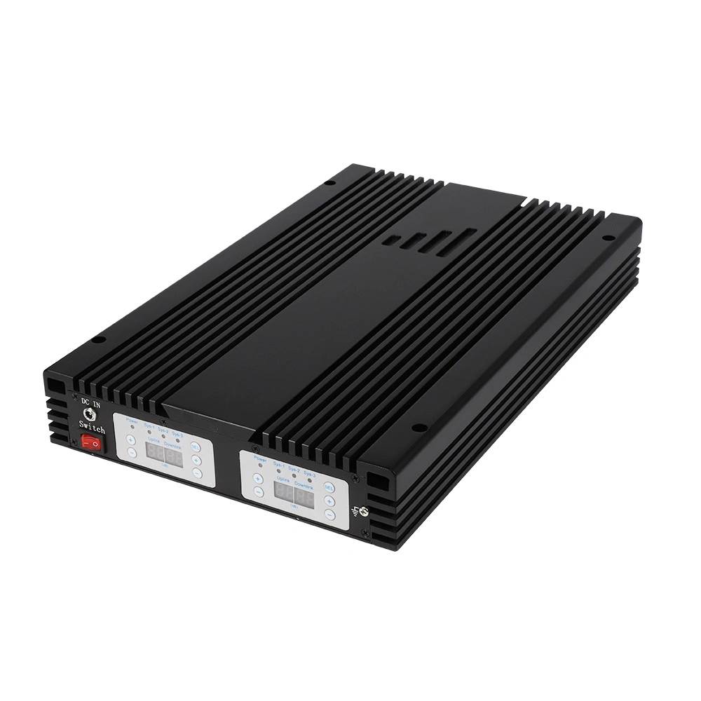
A repeater on its own is half a system. The unit is designed to connect by coaxial cable to a donor antenna placed outside the building where BTS signal is available, and to a service antenna inside that pushes coverage into blind spots. If you are quoting a project, those four items — plus a wall mount — are what the customer is actually paying for.
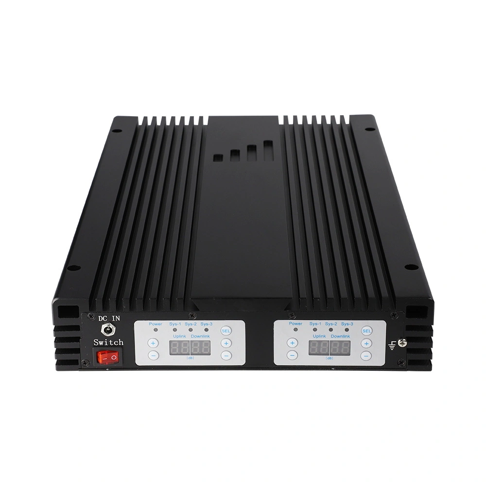
The repeater is a wall-mounted indoor unit measuring 268 × 439 × 58 mm and weighing under 9.5 kg.
Buyer decision: confirm in your order whether you are buying the repeater alone or a configured kit. Antenna gain, cable type and cable length are site variables and should be agreed together with the repeater specification, not after it.
Five bands are amplified simultaneously, and each one has a defined uplink and downlink window. Match these windows against the bands your market's operators actually use — a five-band unit is only efficient where most of those bands are live.
Swipe sideways to see every column →
| Band | Uplink (MHz) | Downlink (MHz) | Commonly associated with |
|---|---|---|---|
| LTE800 | 832–862 | 791–821 | 4G LTE coverage layer |
| EGSM900 | 880–915 | 925–960 | 2G voice and SMS, plus legacy 3G |
| 1800 MHz (DCS) | 1710–1785 | 1805–1880 | 2G and 4G LTE 1800 |
| WCDMA 2100 | 1920–1980 | 2110–2170 | 3G UMTS and LTE 2100 |
| LTE2600 | 2500–2570 | 2620–2690 | 4G LTE capacity layer |
Wide band or selective band: this unit is described as a wide band signal booster, and the page states that a selective band booster can be customised. That choice is the first procurement decision — a wide band unit covers mixed-operator buildings, while a selective band build is aimed at deployments where only one or two windows matter and everything else is unwanted noise.
Every figure below is from the published specification for this model. Uplink and downlink are listed separately because they are not symmetrical — and that asymmetry is what you quote against when a buyer compares you with another supplier's sheet.
The digital display panel carries the intelligent mode setting and the two status LEDs — power and alarm.
| Parameter | Uplink | Downlink |
|---|---|---|
| Max. gain | 70 dB ±2 dB | 75 dB ±2 dB |
| Max. output power | 20 dBm ±2 dBm | 23 dBm ±2 dBm |
| Manual gain control | 31 dB range, 1 dB step | |
| ALC | > 20 dB | |
| Band width | Wide band | |
| Ripple in band | 8 dB | |
| Noise figure | ≤ 6 dB | |
| VSWR | ≤ 2.0 | |
| Intermodulation | ≤ −40 dBc | |
| Spurious emission | 9 kHz–1 GHz ≤ −36 dBm; 1–12.75 GHz ≤ −30 dBm | |
| Time delay | ≤ 1.5 μs | |
| Frequency stability | ≤ 0.01 ppm | |
| MTBF | > 50,000 hours | |
| Impedance | 50 ohm | |
| RF connector | N-Female | |
| Power supply | AC 90–264 V, DC 10 V / 10 A | |
| Cooling | Heatsink convection cooling | |
| Operating temperature | −10 °C to +55 °C | |
| Humidity | < 90 % | |
| Environmental protection | IP40 | |
| Installation type | Wall installation | |
| Dimensions | 268 mm × 439 mm × 58 mm | |
| Weight | < 9.5 kg | |
Buyer decision: the 70 dB uplink ceiling and the 31 dB manual gain range together define how much headroom you have on site. On a weak-donor site you need the gain; on a site close to a base station you need the attenuation — and the ALC working above 20 dB to hold the unit back from over-saturation.
Four common deployment situations, and the parameter on this repeater that decides whether it fits. Use this as the first filter before you send a quotation.
Staff handsets sit on different networks and different generations, so the building needs more than one frequency window amplified.
Decision: wide band build covering all five windows — 800, 900, 1800, 2100 and 2600 MHz.
Where the traffic is 2G voice and a single LTE layer, amplifying five wide windows adds cost without adding usable signal.
Decision: ask for a selective band variant rather than the standard wide band unit.
A strong donor signal is a risk, not a bonus: too much input drives the amplifier into over-saturation and raises interference.
Decision: rely on the 31 dB manual gain range in 1 dB steps and the ALC range above 20 dB; confirm green alarm LED at commissioning.
Coverage has to survive distance, so the specification must supply enough gain and output to fill the space.
Decision: plan against the stated 500–3000 m² unobstructed figure with 75 dB downlink gain and 23 dBm downlink output.
The published figure is about 500–3000 m² without block or obstruction. That qualifier carries most of the weight: concrete walls, metal partitions, ducting and rack rows cut the usable radius considerably, which is why two identical units can perform very differently in two buildings.
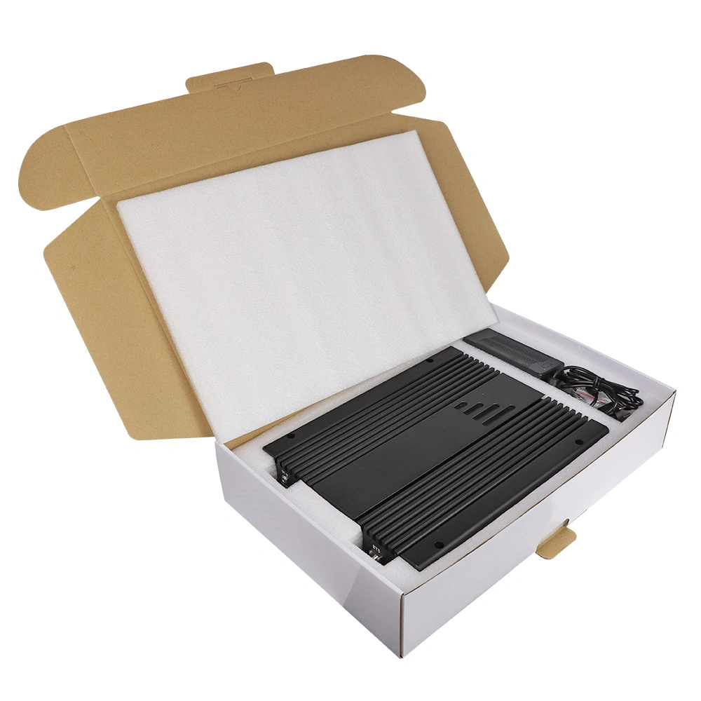
Wall installation with convection cooling: allow clearance around the 268 × 439 × 58 mm casing for airflow.
Written from the buyer's side of the table. Each item below corresponds to a declared parameter on this model, so you can ask for it in writing rather than accept it on a datasheet.
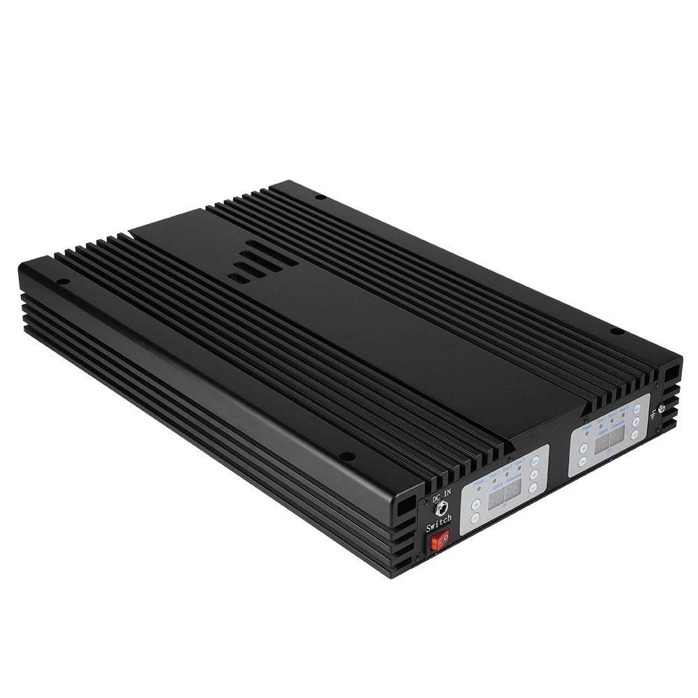
Power LED and alarm LED states should be demonstrated on the sample before a batch is approved.
The fastest route to a usable quotation is a short, precise brief. Include the items below and the reply can be built against the declared figures rather than guesses.
Custom band plans, distributor quantities and project pricing are all handled through the same enquiry channel — there is no checkout on this site, every order starts as a conversation.
Share your band requirements and quantity, and the team will respond with configuration and lead-time information for your project.
Contact UsProduct reference: 20dBm 5-band 2G/3G/4G repeater, 800 / 900 / 1800 / 2100 / 2600 MHz, ALC & MGC, LCD display.
Keep adjacent product options together for a faster catalog comparison.
UAV Detection and Positioning Module Real Time Drone Speed Altitude Flight Track Monitoring
View product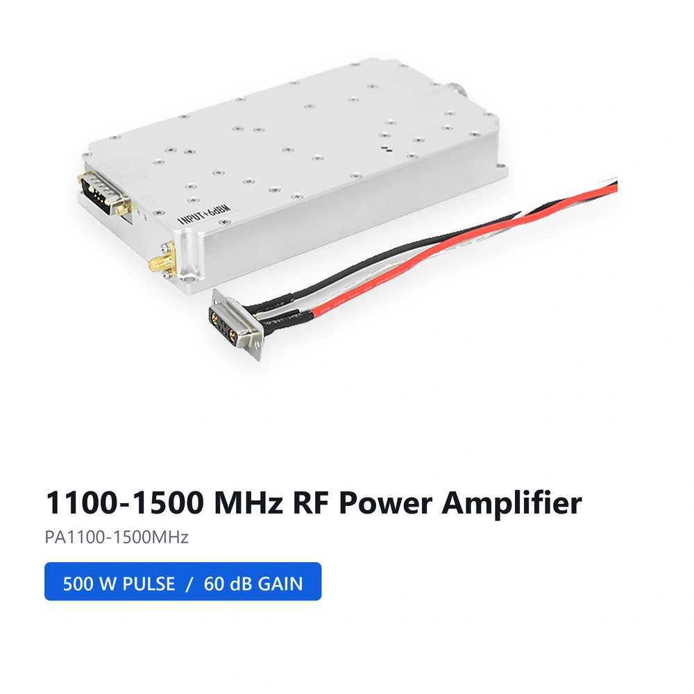
500W 1100-1500MHZ 1.5G Drone Jammer Module anti fpv System RF Power Amplifier Module
View product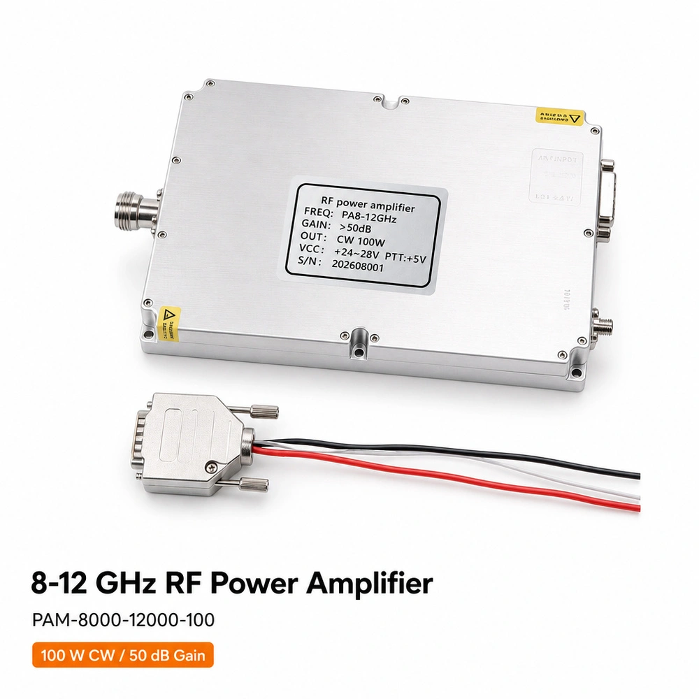
Anti-Drone Module Customized 100W RF Power Amplifier Module Anti-Drone for 8000-12000MHz Wireless Counter FPV
View productit covers 800, 900, 1800, 2100 and 2600 mhz for 2g, 3g and 4g. the uplink windows are 832–862 / 880–915 / 1710–1785 / 1920–1980 / 2500–2570 mhz, and the downlink windows are 791–821 / 925–960 / 1805–1880 / 2110–2170 / 2620–2690 mhz.
maximum gain is 70 db ±2 db on the uplink and 75 db ±2 db on the downlink. maximum output power is 20 dbm ±2 dbm uplink and 23 dbm ±2 dbm downlink.
manual gain control gives a 31 db adjustment range in 1 db steps, so installers can turn the gain down on strong-donor sites. automatic gain control is specified at more than 20 db and works to prevent over-saturation, maintain voice quality and reduce interference to the network.
the listed coverage is about 500–3000 m² without block or obstruction. the unit is designed for indoor wall installation, uses heatsink convection cooling, and is rated for −10 °c to +55 °c, below 90% humidity and ip40 environmental protection.
the power led shows power status. the alarm led shows red for self-oscillation or a strong input signal, and green for normal operation, so it helps confirm whether the donor input and antenna separation are suitable at commissioning.
the standard unit is a wide band signal booster covering all five bands, and the page states that a selective band booster can be customized. for distributor or tender projects, confirm the exact uplink and downlink windows, connector scope and quantity in the inquiry.
